Posts

Showing posts with the label EMI EMC

EMC design considerations

Image
Any electronic product consists of various modules, where each module has to communicate with the other for its operation or to report the status. With the ever-growing demand for faster processing speeds, better response time and more throughputs, always narrow down to highspeed circuits. If not contained properly, the signal flowing t h r o u g h these circuits may radiate energy and can cause problems in the operation of devices in the near vicinity. Now, engineers must consider not only the actual logic on the PCB, but also several other aspects that affect the circuit, including power consumption, PCB size, environment noise, andEMC. The following 10 key EMC design considerations can serve as guidelines and describe how hardware engineers can address EMC issues during the PCB design phase for a system free of EMC faults: 1. Ground Planes : A low-inductance ground system is the most vital element when designing a PCB for minimizing EMI. Maximizing the ground area on a PCB re

placement of connectors and groundings to reduce EMI

Cables and Connectors (1) Cables should be grouped according to their function such as power, analog, digital, and RF. (2) Separate connector assemblies should be used for analog and digital signals. (3) Analog and digital connectors should be located as far apart as possible. (4) Analog and digital signal pins should be separated by unused grounded pins when sharing the same I/O connector. (5) Individual pins should be used inside the I/O connector for each signal return so that all return circuits remain separated. (6) Connector crosstalk may be reduced by using separate power and ground pins for each signal and by reducing the circuit’s loading and current flow.   (7) Cable shields should be grounded to equipment housing at the I/O points. (8) Shielded I/O cables are most effective if grounded at both ends. (9) Cable common mode currents should be removed at the equipment’s metal housing prior to internal connections. (10) Cables should be rou

Capacitor Parasitics - Designing for EMI

During your PCB design, an important thing to consider is placement of decoupling capacitors on your PCB for EMI. Capacitors do many things. They filter voltage droops, they present a 'brick wall' for transients, and they try their best to kill any EMI noise on your power rails. One of the most common functions though, is this filtering of EMI noise going into and coming out of the chip on your PCB design. It's supposed to be attached as close as possible to the input power pin of your part with the shortest, fattest trace possible, but surely you're already aware of this (it's also supposed to have the shortest current loop possible between the chip and part, but that's beyond the scope of this article).   For the sake of explanation, you can think of a capacitor as really a capacitor in line with an inductor. Crazy? Yes it is, but it's also unavoidable. If you found a wire lying on the ground and pick it up, it is inherently an inductor of some val

Decoupling, Bypassing and Filtering

Decoupling, Bypassing and Filtering ( 1) EMI filters can be used as a shunt element to divert electrical currents from a trace or conductor; as a series element to block a trace or conductor current; or they may be used as a combination of these functions.    Selection of the filter elements should always be based on the desired frequency range and component characteristics.    A low pass filter can be useful for reducing most high frequency EMI problems.    It incorporates a capacitive shunt and series resistance or inductance.    However, at frequency extremes, the capacitor can become inductive and the inductor can become capacitive causing the filter to act more like a band-stop filter.     The filter design type should be based on the overall impedance at the circuit’s point of application for proper match.    A T-filter design is effective for most EMI applications and is ideal for analog and digital I/O ports.    (2) Capacitors may be used for signal filtering and powe

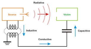
Identifying Potential EMI Sources and Victims

Image
As mentioned in my previous Article i am trying to elaborate the EMI source and victims. After seeing the word EMI you must be thinking  what is it? Below is the small definition of EMI. Electromagnetic Interference (EMI) The process where disruptive electromagnetic energy is transmitted from one electronic device to another via radiated or conducted paths. –  Radiated Emissions -The component of RF (roughly 10kHz to 100GHz) energy transmitted through a medium, usually free space (air), as an electromagnetic field. –  Conducted Emissions -The component of RF energy transmitted as a propagating wave generally through a wire or interconnect cable. LCI (Line conducted interference) refers to RF energy in the power cord.   A typical circuit board may have dozens, hundreds or even thousands of circuits. Each circuit is a potential source of energy that might eventually be coupled unintentionally to other circuits or devices. Each circuit is also a potential victim of unin

Strategies for Laying Out Printed Circuit Boards.

Image
Most board designers employ a list of guidelines to help place components and route traces. For example, a typical guideline might be "minimize the length of all traces carrying a digital clock signal." Often, a designer is not familiar with the reason for the guideline or does not fully understand the consequences of violating the guideline for a particular application. Quiz Question Suppose you're laying out a high-speed multi-layer printed circuit board and you need to route a trace carrying a high-frequency signal from a digital component to an analog amplifier. You want to minimize the chance of having an electromagnetic compatibility (EMC) problem, so you search the web for EMC design guidelines and you find three guidelines that seem to pertain to your situation: 1.         minimize the length of high-speed traces; 2.         always gap any solid planes between analog and digital circuits; and 3.         never let a high-speed trace cross over a gap i