Posts

Showing posts from 2015

Do's and Don'ts for PCB Layer Stack-up

Image
Each day the electronic gadgets complexity increases with the miniaturization requirements, boards are becoming much denser. Multilayer PCB technology can satisfy today’s miniaturization board requirement. Multilayer PCBs has more than two layers of PCBs, arrangement of layer should be done with great care because inefficient layer arrangement will lead to the noisy board with unexpected performances. This article addresses the layer stack-up basics and the general layer stack-up considerations. 2 . Layer stack-up basics  Layer stack-up specifies the proper arrangement of circuit board layers for multilayer boards before starting board layout design.  Stack-up mainly defines which layers should be solid power and ground planes, the substrate (dielectric constant), and the spacing between layers.  While planning a layer stack-up, also compute the desired trace dimension and minimum trace spacing. SIDE VIEW    Multilayer boards are made up of one or mo

Difference between through hole and Surface mount components

Image
As technology grows the demand for less weight and smaller size component increases. This leads to new improved technology known as   surface mount technology   (SMT). Surface mount components are similar to plated through hole as far as there electrical function is concerned but the key difference is in their size. The small size of surface mount components (SMC) provides better electrical performance. Surface mount components are placed or mount directly on Printed circuit board (PCB) which means they do not require hole for mounting the component. They can be directly soldered on track side. Surface mount components have different shape leads and they have little circular at bottom etc for soldering as shown in figure below. SMD devices are mainly found in multi-layer PCB where size of device is major concern. They can also be used on boards or devices which contain both through hole and SMC because some components like transformer, heat sink are not suitable for SMC.

Common of Surface Mount Devices (SMDs)

Image
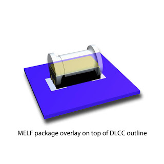
The taxonomy of surface mount devices (SMDs) is so expansive and ever-changing that covering it in full would be impossible. But here are several types that are very common and very important to know. MELF (Metal Electrode Face Bonded) : Consisting of two terminals bonded to a cylindrical body, these SMD components are less expensive than flat chips but require special handing during assembly. Furthermore, one of their biggest disadvantages is their tendency to roll off solder pads during assembly. Generally speaking, they come in the form of diodes, resistors, and capacitors. SOT Transistors and Diodes : These are usually rectangular and easy to place, though they're a bit outdated. The most common SOTs are SOT 23, SOT 89, SOT 143, and SOT 223. Its most common packaging is tape & reel. Integrated Circuits (ICs) : Small outline Integrated Circuit (SOIC)  – These are good SMT alternatives to the duel in-line package (DIP), due to their dramatically reduce

Types of Components Used in PCB and their explanations.

Image
In recent years, semiconductor packaging has evolved with an increased demand for greater functionality, smaller size, and added utility. A modern PCBA design has two main methods for mounting components onto a PCB:  Through-Hole Mounting  and  Surface Mounting.   Through-Hole Components Through-Hole Mounting (THM): Through-hole mounting is the process by which component leads are placed into drilled holes on a bare PCB. The process was standard practice until the rise of surface mount technology (SMT) in the 1980s, at which time it was expected to completely phase out through-hole. Yet, despite a severe drop in popularity over the years, through-hole technology has proven resilient in the age of SMT, offering a number of advantages and niche applications: namely, reliability.   Through-hole components are best used for high-reliability products that require stronger connections between layers. Whereas SMT components are secured only by solder

Few Abbreviation related to PCB designing and their explanations.

ADC - Analogue to Digital Converter  AGND - Analogue Ground - separate ground for analogue signals  Auto-MDIX  -Automatically Medium Dependent Interface Crossing - a PHY with Auto-MDIX is able to detect whether RX and TX need to be crossed (MDI or MDIX)  CAD -Computer-Aided Design CAN -Controller Area Network - a bus that is manly used in automotive and industrial environment  CDMA -Code Division Multiplex Access - an abbreviation often used for a mobile phone standard for data communication  CEC -Consumer Electronic Control - a HDMI feature that allows to control CEC compatible devices  CPU -Central Processing Unit  CSI -Camera Serial Interface  DAC -Digital to Analogue Converter  DDC -Display Data Channel - an interface for reading out the capability of a monitor, in this document DDC2B (based on I2C) is always meant  DRC -Design Rule Check - a tool for checking whether all design rules are satisfied in a CAD tool  DSI- Display Serial Interface  DVI -Digit

Understanding PCB Materials and Specifications

Image
When you give a PCB for fabrication, you need to specify details on PCB materials, impedance controls, finish, copper thickness and so on. Most of the details are so common that they are always assumed. However still it is better to know them. Below is a screenshot of quotation submitted by a fabricator for a PCB design  Let us understand each term one by one and things related to them 1) 4 layer specifies NUMBER OF LAYERS - This means the number of conducting layers. The layers may be either routing layer or plane layer. The commonly used no. of layers are 1, 2, 4, 6, 8 and other even numbered layers. Odd number layer boards may be formed but they are not standard boards and doesn’t offer any savings. The PCB materials used for 3 or 4 layers would almost be same. Routing layers contains tracks while plane layer are generally used to connect power or ground. Plane layers have plane of copper from which connections are drawn up or down wherever needed. Islan