Identifying Potential EMI Sources and Victims
As mentioned in my previous Article i am trying to elaborate the EMI source and victims.
After seeing the word EMI you must be thinking what is it?
Below is the small definition of EMI.
Electromagnetic Interference (EMI)
The process where disruptive electromagnetic energy is transmitted from one electronic device to another via radiated or conducted paths. –
Radiated Emissions -The component of RF (roughly 10kHz to 100GHz) energy transmitted through a medium, usually free space (air), as an electromagnetic field. –
Conducted Emissions -The component of RF energy transmitted as a propagating wave generally through a wire or interconnect cable. LCI (Line conducted interference) refers to RF energy in the power cord.
A typical circuit board may have dozens,
hundreds or even thousands of circuits. Each circuit is a potential source of
energy that might eventually be coupled unintentionally to other circuits or
devices. Each circuit is also a potential victim of unintentionally coupled
noise. However, some circuits are much more likely than others to be a noise
source and other circuits are much more likely to be victims. EMC engineers
(and board designers) should be able to recognize those circuits that are
potentially good sources and those that are potentially most susceptible.
Circuits of particular interest are discussed below.
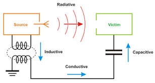

Electromagnetic Interference (EMI) is caused by undesireable radiated electromagnetic fields or conducted voltages and currents. The interference is produced by a source emitter and is detected by a susceptible victim via a coupling path. The coupling path may involve one or more of the following coupling mechanisms:
1. Conduction - electric current
2. Radiation - electromagnetic field
3. Capacitive Coupling - electric field
4. Inductive Coupling - magnetic field
Conducted noise is coupled between components through interconnecting wires such as through power supply and ground wires. Common impedance coupling is caused when currents from two or more circuits flow through the same impedance such as in power supply and ground wires.
Radiated electromagnetic field coupling may be treated as two cases. In the near field, E and H field coupling are treated separately. In the far field, coupling is treated as a plane wave coupling.
Electric field coupling is caused by a voltage difference between conductors. The coupling mechanism may be modeled by a capacitor.
Magnetic field coupling is caused by current flow in conductors. The coupling mechanism may be modeled by a transformer.
Some typical external noise sources into a radio receiver include radiated electric field coupling from: high-voltage power lines, broadcast antennas, communications transmitters, vehicle ignition systems and electric machinery. Most conducted coupling from external sources occurs through the ac power lines.
Typical radio interference to other equipment includes radiated electric field coupling to: TV sets, broadcast receivers, telephone lines, appliances, and communications receivers. Most conducted coupling to other equipment occurs through the ac power lines.
The most common methods of noise reduction include proper equipment circuit design, shielding, grounding, filtering, isolation, separation and orientation, circuit impedance level control, cable design, and noise cancellation techniques.
Electromagnetic radiation involves electric (E) and magnetic (H) fields. Any change in the flux density of a magnetic field will produce an electric field change in time and space (Faraday's Law). This change in an electric field causes another change in the magnetic field due to the displacement current (Maxwell). A time-varying magnetic field produces an electric field and a time-varying electric field results in a magnetic field. This forms the basis of electromagnetic waves and time-varying electromagnetics (Maxwell's Equations). Wave propagation occurs when there are two forms of energy and the presence of a change in one leads to a change in the other. Energy interchanges between electric and magnetic fields as the wave progresses.
Electromagnetic waves exist in nature as a result of the radiation from atoms or molecules when they change from one energy state to another and by natural fluctuations such as lightning. The technology of generating and processing electromagnetic waves forms the basis of telecommunications.
Electromagnetic Effects (EME) includes many electromagnetic environmental disciplines such as Electromagnetic Compatibility (EMC), Electromagnetic Interference (EMI), and Electromagnetic Pulse (EMP).
Electromagnetic Interference (EMI) is electromagnetic energy that adversely affects the performance of electrical/electronic equipment by creating undesirable responses or complete operational failure. The interference sources may be external or internal to the electrical or electronic equipment and they may propagate by radiation or conduction. This discipline includesRadio Frequency Interference (RFI), the term which was originally used to describe most electrical interference. EMI is usually divided into two general categories to help in analyzing conducted and radiated interference effects: narrowband and broadband.
Narrowband Emissions - a narrowband signal occupies a very small portion of the radio spectrum. The magnitude of narrowband radiated emissions is usually expressed in terms of volts per meter (V/m). Such signals are usually continuous sine waves (CW) and may be continuous or intermittent in occurrence. Communication transmitters such as single-channel AM, FM and SSB fall into this category. Spurious emissions, such as harmonic outputs of narrowband communication transmitters, power-line hum, local oscillators, signal generators, test equipment, and many other man made sources are narrowband emissions.
Broadband Emissions - a broadband signal may spread its energy across hundreds of megahertz or more. The magnitude of broadband radiated emissions is usually expressed in terms of volts per meter per MHz (V/m/MHz). This type of signal is composed of narrow pulses having relatively short rise and fall times. Broadband signals are further divided into random and impulse sources. These may be transient, continuous or intermittent in occurrence. Examples include unintentional emissions from communication and radar transmitters, electric switch contacts, computers, thermostats, motor speed controls, thyratron circuits, ignition systems, voltage regulators, pulse generators, arc/vapor lamps, and intermittent ground connections. They may also result from galactic and solar noise, lightning electromagnetic pulses, and by radio frequency pulses associated with electrostatic discharges.
I will continue this topic in my next Article..
keep reading and enjoy reading...
Thanks,
Ruby


Comments
Post a Comment